

SETTINGS Screen
Accessed by pressing SETTINGS on the main screen. It contains all the console’s configuration options.1 CONFIGURATION MENU
- Configuration options are displayed in tabs on the left side of the screen: INPUTS, OUTPUTS, GPIO, SYS CONFIG, STREAMING, AoIP (Dante), USERS.
- When accessing SETTINGS, the first menu item, which is INPUTS, is loaded by default.
- Some options can also be accessed from the context menu in the lower zone.
- Tapping an option displays the corresponding controls and values for that option on the screen.
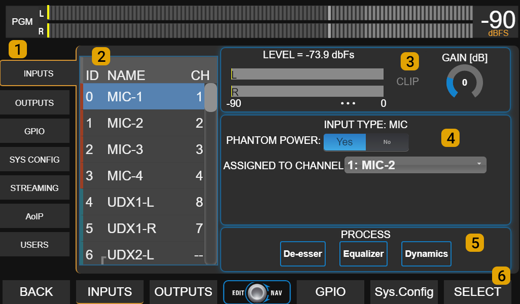
INPUTS SETTINGS
2 Input List
Displays all available inputs.An input is selected by rotating the encoder.
On the right, the options and configuration for the selected input are displayed.
- The ID number on the left of each input is fixed and corresponds to the internal order.
- The number on the right indicates the assigned channel for that input.
- Stereo inputs are shown grouped in L/R pairs.
- If they are configured as
STEREO, they are grouped as a pair. - If they are in
MONO, the left and right channels are unlinked and can be selected separately.
- If they are configured as
3 Input Gain
Controls the gain of the selected input.To modify the value, turn the encoder.
Pressing the encoder toggles the control between list navigation and gain adjustment. The level meter shows the peak value of the signal at the input (dBfs). Quick gain adjustment:
- For line inputs, play music with low dynamic range (e.g., modern pop).
For microphone inputs, speak continuously at an appropriate level and correct distance. - Position the channel fader in the normal working zone (marked between -10 dB and -20 dB).
- Adjust the gain until the PROGRAM VU meter reads around 0 VU. Observe the slow (VU) reading, not the dBfs peak, as the peak will always be “floating” above the VU value.
This gain control is also shown on the channel (CHANNEL) screen. The gain adjustment can be made from either of these screens.
4 Input Options
The available options depend on the selected input type:- INPUT TYPE: Indicates the input type (MIC, LINE, UDX, USB, AES).
- MODE: Stereo or mono. In mono, the L/R channels are configured as independent inputs.
- ASSIGNED TO CHANNEL: Channel to which the signal from the selected input is sent.
The channel is chosen from the dropdown menu. This option is also shown on the CHANNEL screen. - PHANTOM: Available only for MIC inputs and for UNIDEX inputs with UDX 2MIC adapters. Enables/disables 48 V power.
- UDX TYPE: Available only on UNIDEX inputs. Defines the model of adapter connected.
If the UNIDEX input is used as a balanced line,UDX TYPEmust beLINE(default).
5 Process
Shortcuts to the processes available for the input.In normal operation, they are accessible from the PROCESS and CHANNEL screens.
6 Select
Activates SELECT mode, allowing you to choose a channel from the CUE/SELECT buttons and view the assigned input.The encoder always navigates through the input list, even with SELECT active.
OUTPUTS SETTINGS
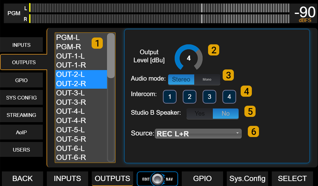
1 Output List
Displays all available outputs.Selection is made by rotating the encoder or by touching the screen directly.
On the right, the configuration options for the selected output are shown.
2 Output Gain
Adjusts the output level. Depending on the output type, the adjustment may be given in dBu or dBfs.- Analog outputs: the level is expressed in dBu referenced to 0 VU (default: +4 dBu).
- Digital outputs: the gain is expressed in dB.
When the gain is zero (default), the level matches the meter scale
(0 VU = –20 dBfs, 1 kHz @ 0 VU).
The PGM, REC, and AUX meters on the main screen show the bus level before the output gains. If a digital gain is modified, the actual output level may differ from the indicated one, creating a risk of clipping not visible on the meters.
3 Audio Mode
Allows configuration of the output asstereo or mono. In mono mode, the left and right channels of the pair are used as independent outputs (for example, to feed UDX 2TEL adapters that send mono signals to the phone lines).
6 Source
Only available on assignable outputs. Defines the signal sent to that output.On outputs with the MIX-MINUS option, defines the signal source for the output in DIRECT mode.
Sources available on the outputs for the UX-24:\
PGM, REC, AUX, VBUS, CUE, STUDIO HEADPHONES, TALKBACK, MIC-1, MIC-2, MIC-3, MIC-4, UDX-1 to UDX-8
Sources available on the UX-18 outputs:
Mix-Minus Feeds
A MIX-MINUS output sends a mix from which the signal of an associated input is SUBTRACTED. It is used, for example, for the return feed to a phone line, preventing the call audio from re-entering the system and causing feedback. The line is sent a PGM Mix-Minus, which is the PGM signal MINUS the phone line audio. The stereo outputs (5 to 8 on UX24; 1 to 4 on UX18) and all USB outputs can be configured as Direct or Mix-Minus.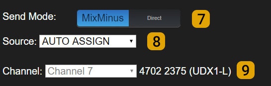
7 Send Mode
- Direct: Normal working mode for the outputs. mix-minus is disabled. The signal defined in SOURCE is sent directly to the output.
- Mix-Minus: The signal from an associated input is subtracted from the output signal.
8 Mix-Minus Source
Defines the bus on which the subtraction is performed:PGM, REC, AUX, VBUS, or AUTO ASSIGN.In AUTO ASSIGN, the bus is chosen automatically based on priority: Priority 1 - PGM
Priority 2 - REC
Priority 3 - AUX
Priority 4 - VBUS For example:
- If a channel is assigned to PGM and REC, the mix-minus is performed on PGM.
- If it is assigned only to REC and AUX, it is performed on REC.
9 Mix-Minus Channel
Displays the input associated with the selected output and the channel assigned to that input.These fields cannot be edited.
Each output in mix-minus mode has its associated input preconfigured. Default MIX-MINUS assignment table for the UX24. For the UX18 it is the same, except outputs OUT 5 to 8 are replaced by OUT 1 to 4.
Special Options for Talk-Back and Intercom
Intercom (UX24 only)
Enables intercom feed to that output. When the assigned Intercom button is pressed on the console, the order microphone audio interrupts the signal present at the output. It is used, for example, to set up separate talkback feeds to headphone monitoring.Studio B Speakers (UX24 only)
Allows using the output to power the monitor speakers of a Studio B.When microphones assigned to this studio are activated, the output is automatically muted.
Talk-Back Channel and Studio Talk-Back Link (UX18 only)
These options allow you to configure the UX18 to work with separate talkback channels and headphone groups. This wiring is explained in Configuring StudioBox with Dual Talk-Back Channel. Talk-Back Channel: Links the output to the talk-back mode of a hardware channel (does not apply to virtual channels).- Talkback is activated from the channel by holding down the CUE/SELECT button.
- When activated on a channel linked to an output, the talkback microphone signal (internal or external) is sent only to that output, interrupting the current audio.
- The dropdown menu allows you to choose:
- Channels 1 to 6
- A GROUP channel (A, B, C, or D)
- Disable the function (unassigned)
- When the Talk-Back button is pressed, the talkback microphone is sent to the STUDIO output and to all outputs that have Studio Talk-Back Link enabled.