

GPIO Control
The GPIO (General Purpose Input/Output) connector provides inputs and outputs that allow control of console functions (GPI), such as microphone activation; or control of external devices (GPO), such as indicator lights or audio processing.- GPI supports trigger signals of 5-15V/150mA (active high).
- GPO 1 to 7 are of the _“open drain” type. _They function as switches, connecting the output to ground. They support signals of 5–24 V / 250 mA.
- PIN 8 supplies DC voltage (differs depending on the console model, see below). It can be used to trigger GPIs directly (with a switch). Or to power an external device activated via a GPO (for example, a light or a small relay)
Pin-out and Configuration
GPIO UX24
GPIO UX24
DB15 PIN-OUT (UX24)
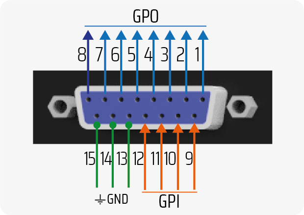
GPO 8 delivers +12V / 250 mA when active. 0V when inactive.
GPIO CONFIGURATION
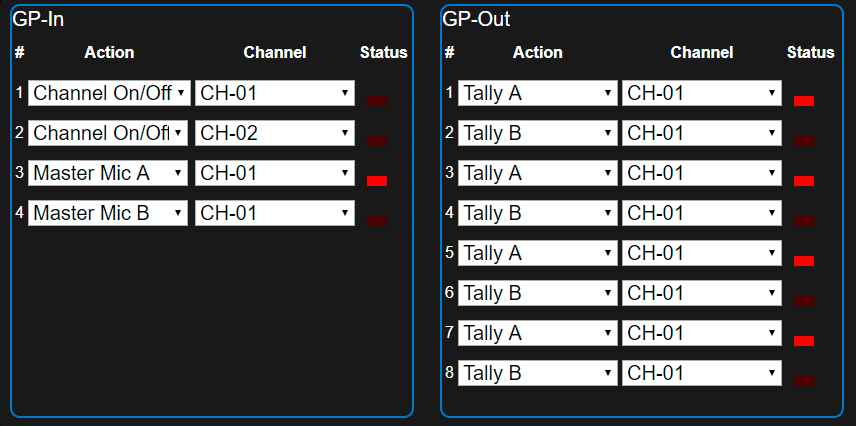
SETTINGS→GPIO screen. Each GP-IN and GP-OUT can be associated with a specific channel and action.The available actions for GPI are:UNASSIGNED; CHANNEL ON/OFF; CHANNEL MUTE; MASTER MIC A; MASTER MIC BThe available actions for GPO are:UNASSIGNED; CHANNEL ON/OFF; TALLY A; TALLY B; TELCO RING; OUTPUT +12V (only GPO8)GPIO UX18
GPIO UX18
DB15 PIN-OUT (UX18)
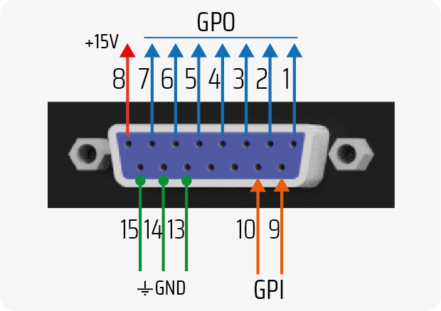
PIN 8 PROVIDES A FIXED VOLTAGE OF +15 VCC / 100 mA (max).
GPIO ACTION CONFIGURATION
The actions that trigger the GPIO are defined in theSETTINGS→GPIO screen. Each GP-IN and GP-OUT can be associated with a channel and a specific action.The available actions for GPI are:UNASSIGNED; CHANNEL ON/OFF; CHANNEL MUTE; MASTER MIC AThe available actions for GPO are:UNASSIGNED; CHANNEL ON/OFF; TALLY A; TALLY B; TELCO RINGGPIO Application Cases
LED Gooseneck Arm (GPO)
The GPO 1 to 7 outputs can function as electronic switches, controlling LEDs connected to an external power supply, provided the current draw does not exceed 250 mA.If the current draw exceeds 250 mA, an external relay must be used for switching. It is recommended to use GPO 8 to directly drive a 12 V coil relay with a current draw of up to 250 mA.
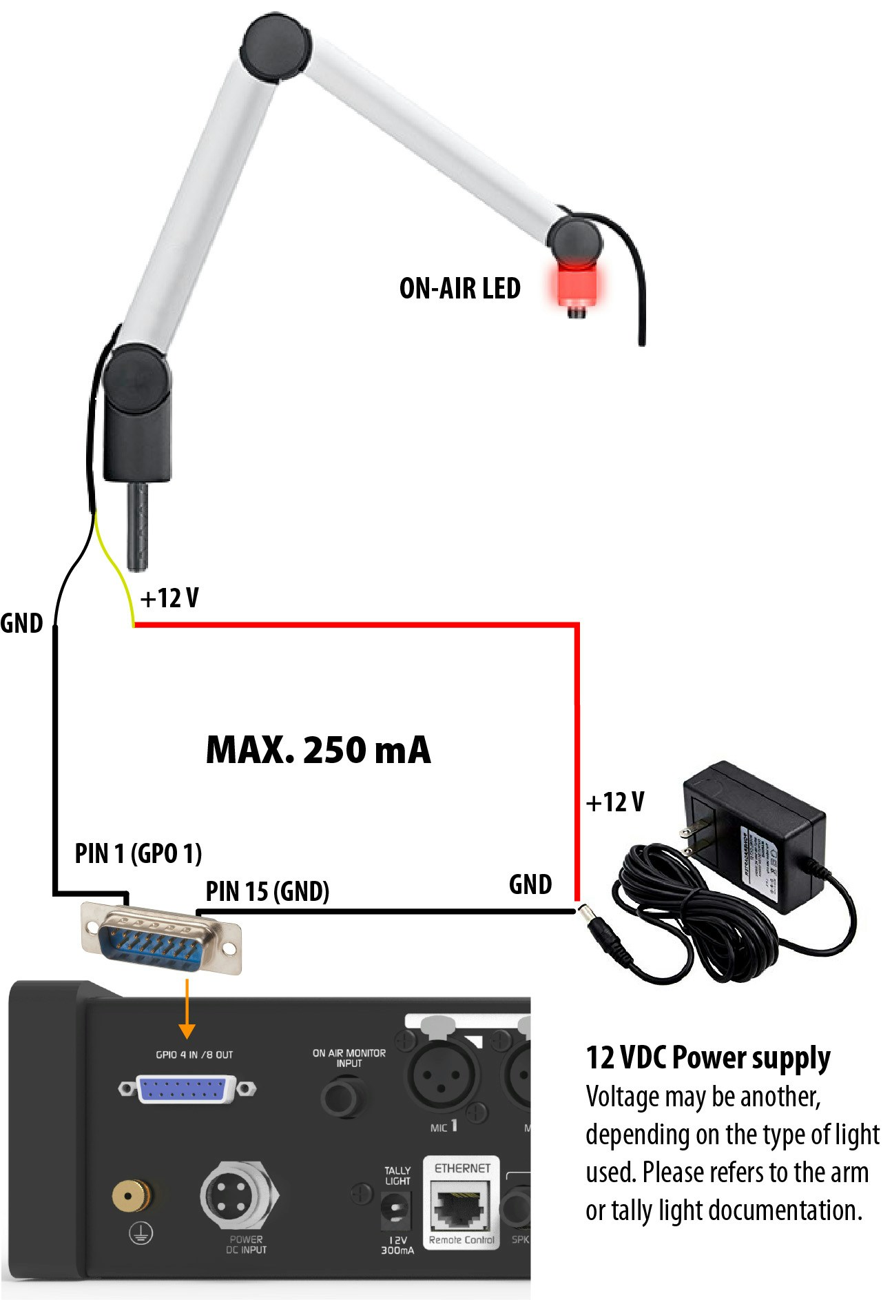
- GPO 1 → ON/OFF MIC Channel 1
- GPO 2 → ON/OFF MIC Channel 2
- etc.
Mute Microphone (GPI Usage)
The GPI inputs allow automated actions to be executed on the console. One of the most useful is the temporary channel mute (MUTE), ideal for implementing a cough button in the studio. This allows the presenter to mute their microphone without operator intervention. The following example shows the connection of a momentary push button to activate GPI 1.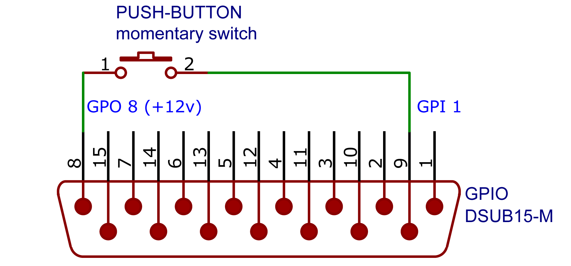
- GPI 1 is configured with the MUTE action and is associated with the desired channel.
- GPO 8 delivers a fixed voltage.
”ON-AIR” Indicator Lights (Tally Light)
On the rear panel of the console is the 12 V / 250 mA output for connecting “ON-AIR” indicator lights.The UX24 model handles two studios and has two Tally Light outputs: Studio A and Studio B.
- Up to two Solidyne LA100 on-air lights can be connected per output.
- For lights from other brands, ensure the total consumption does not exceed 250 mA.