

Physical Channels
The UNIDEX UX24 console features 24 channels. The main chassis includes 12 physical channels with 100 mm soft-touch faders. An additional 12 channels can be operated via the touchscreen or remotely via the web interface. Optionally, up to two UX6 expansion modules (6 faders each) can be added to achieve 18 or 24 physical channels.
- On physical channels, assignment to PGM, REC, and AUX is done using three quick-access buttons. When the channel is assigned, the button lights up in orange.
- For all channels, assignment to VBUS is done from the CHANNEL screen in the main menu or via the web control.
2 CUE/SELECT BUTTON Performs three functions:
- CUE: Pre-fader monitoring. Allows listening to the signal present on the channel before the fader and the ON-AIR button.
- SELECT: Channel selection for adjustments and configuration.
- TALKBACK: TALK-BACK mode is used in communications (TELCO and USB channels assigned to call software). Holding down the CUE button activates the talk-back microphone for speaking.
3 ON-AIR BUTTON Activates the channel.
When turned on, the signal is sent to the assigned buses according to the fader level.
4 OLED DISPLAY Displays:
- Pre-fader signal level. The CLIP indication means the input signal reaches 0 dBfs and requires reducing the gain.
- Channel name or label.
-
Status in special modes such as SELECT or TELCO.
About OLED brightness
The brightness is reduced after 5 minutes of inactivity and turns off after 15 minutes.
Any action on the controls reactivates the display.
5 MAIN FADER Controls the signal level on the mix buses.
If the level is adjusted from the CHANNEL screen or remotely via the web, the actual attenuation value may not match the physical position of the fader (non-motorized). In this case, the OLED display flashes showing the current value.
Moving the fader gradually synchronizes the value.
The SELECT Function
The SELECT mode temporarily converts the CUE buttons into channel selection buttons.When active, the CUE buttons light up in blue and the channel OLED displays show the text SELECT. This function is used to choose a channel and view or make adjustments to it.
The display shows information for a single channel at a time.
For example, to adjust an equalizer, the operator must first select the corresponding channel to view its controls.
SELECT Mode Activation
SELECT mode is activated in any of the following situations:- When pressing CHANNEL on the main screen.
- When pressing PROCESS on the main screen.
- When pressing SELECT on the CHANNEL screen or on a processing screen (EQ, compressor, etc.).
- MODE A
Pressing a CUE/SELECT button displays the channel on screen. SELECT mode remains active, allowing other channels to be selected (this enables easy comparison/review of channels). The CUE/SELECT button of the currently selected channel keeps flashing. - MODE B
Rotating the encoder to scroll through channels. The encoder cycles through all 24 channels, whether physical or virtual.
Virtual Channels
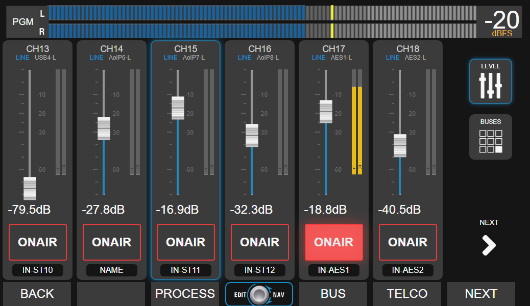
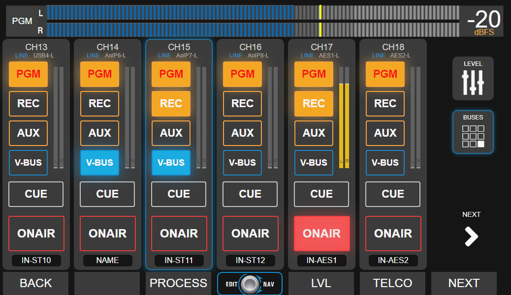
The UNIDEX UX24 handles 12 channels from the onboard display in its standard model, or 6 virtual channels when equipped with a UDX6 fader extension.The VIRTUAL MIXER display allows control of all functions for these channels. When one or more virtual channels are on-air, the VIRTUAL control (encoder) on the main screen flashes red to indicate this condition. To facilitate touch operation, the controls for each virtual channel are divided across two screens. The LEVEL screen shows the faders and ON AIR activation buttons.
Channel Screen
The channel screen displays all values and settings associated with a channel.It includes basic functions, such as input gain adjustment, and advanced options that require special permissions.
Accessing the Channel Screen
-
From the main screen, press the CHANNEL button.
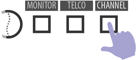
In the menu, the CHANNEL option will change to SELECT to enable toggling it on or off. -
Selecting a channel:
With SELECT active, the CUE/SELECT buttons allow you to choose a channel. While selection mode is active, you can switch between different channels to compare their settings.- Virtual channels are selected by turning the encoder, which cycles through all 24 channels.
- On the screen, the channel name area is displayed in light blue for physical channels and in purple for virtual channels.
-
Exiting SELECT mode:
To confirm and exit, press the SELECT button on the screen or press the encoder.
Selection mode is also automatically canceled when any parameter is modified on the selected channel.
CHANNEL Screen Elements
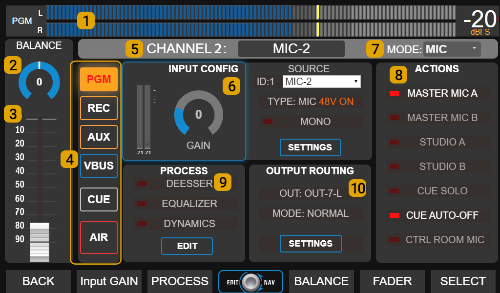
1 VU METER Level indicator visible on all screens.Displays the level of a mix bus, typically PROGRAM, in VU scale with peak hold.
- Touching the PGM label allows switching to display AUX, REC, or VBUS.
- The number on the right indicates the maximum value, in VU or dBfs. Touching the number toggles between units. The VU/dBfs unit change applies to all screens.
2 BALANCE On stereo inputs, adjusts the relationship between left and right channels.
On mono inputs, acts as a pan-pot.
To change the value, touch the control and rotate the encoder. Press the encoder to confirm.
3 CHANNEL LEVEL Represents the physical fader and modifies the signal level on the buses.
On channels with mechanical faders, the on-screen value reflects the physical position. If the level is modified from the screen, the actual value changes but the physical fader does not move (it is not motorized). In this case, the channel’s OLED screen flashes the current value to indicate it differs from the physical fader position.
The output level may differ from the meters due to output gain compensation. Matching occurs only when the output is set to its nominal level (4 dBu for analog outputs).
4 BUSES Show the channel assignments to mix buses.
- On physical channels, they reflect the PGM, REC, and AUX buttons.
- On virtual channels, they allow assignment to any bus.
- On both, they allow assigning the channel to the VBUS, which has no hardware assignment button.
5 NAME Allows assigning a name of up to 10 characters. On physical channels, it is displayed on the channel’s OLED screen.
Touching the name brings up a window for text editing.
6 INPUT CONFIG Includes gain control and information about the assigned input.
- ADMIN profile: full configuration access by touching SETTINGS or reassignment from the dropdown menu.
- Gain: adjustment in decibels via touchscreen and encoder.
7 MODE Defines the channel behavior based on the signal type:
- LINE: for any source other than microphones and communications.
- MIC: for microphone signals, whether onboard inputs, external UDX adapters, or third-party preamps connected to line inputs.
- TELCO: for communications (landlines, VoIP, Bluetooth cell phones), controlling compatible UNIDEX adapters from the TELCO screen.
8 CHANNEL ACTIONS Specific functions based on the channel’s **MODE **.
- CUE SOLO: when CUE is activated on the channel, it turns off CUE on other channels with this option active.
Channels without CUE SOLO active are not affected, allowing CUE to be on in more than one channel at a time.
If all channels operate in CUE SOLO mode, there will be only one CUE active. A common setup is to use CUE SOLO mode on lines (computers and audio players) and normal mode on microphones and TELCO channels. - CUE AUTO OFF: automatically turns off CUE when putting the channel on-air.
- MASTER MIC A/B: assigns the channel to one or both master buttons.
- STUDIO A/B: associates the channel with the “On-Air” signaling (Tally Light) of Studio A; Studio B; or neither.
- CTRL ROOM MIC: If activated, putting the channel on-air mutes the Control Room speaker output (not the Studio output).
9 PROCESS Shows the available processors on the assigned input and their status (active/inactive).
- Turn on/off by touching the name (except BASIC profile).
-
Edit settings from EDIT (ADMIN profile only).
The available processes are not specific to each channel but depend on the assigned inputs.
10 OUTPUT ROUTING Indicates if the channel is associated with a direct output (e.g., UNIDEX adapters for TELCO lines).
Routing configuration is accessible in ADMIN profile from SETTINGS.