

Operational Areas
Audio sources (microphones, computer, and phone lines) enter the console through the input channels, which amplify them.The console mixes all signals to generate a single main signal called Program (PGM). The level of each source is controlled using the main faders. The final mix is sent to the studios via one or more transmission channels. Different areas can be distinguished on the console:
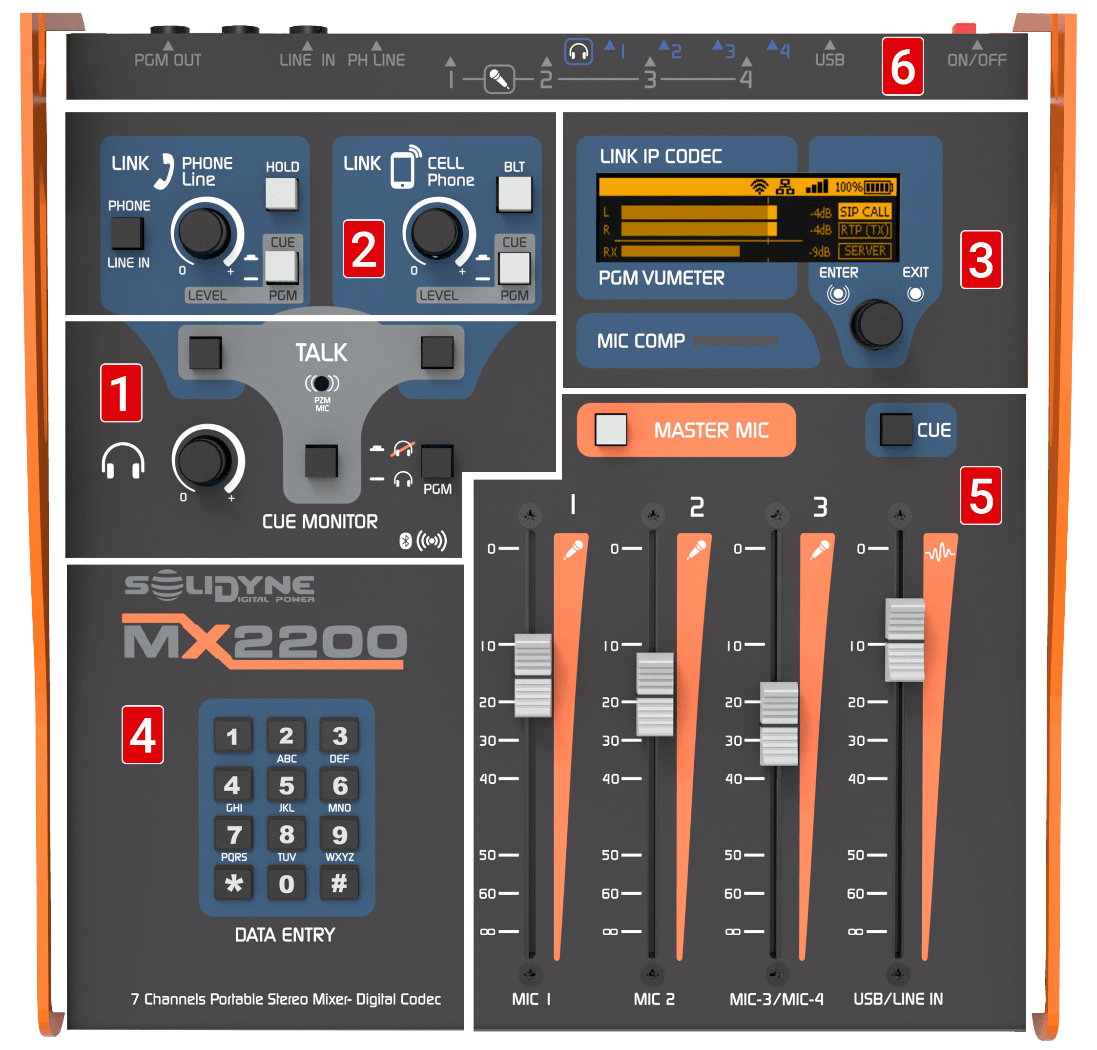
- INTERCOM: controls for speaking to phone lines and headphones.
- TELECOMMUNICATIONS: controls for managing the land line (POTS) and a mobile phone paired via Bluetooth.
- DISPLAY AND ROTARY CONTROL: allow management of Internet connection options (streaming and SIP) and recording.
- DTMF KEYPAD: used to enter characters in text fields and dial (DTMF) on land line (POTS) calls.
- FADERS: allow mixing signals from microphones and lines (USB or analog) to generate the PGM. It is recommended to keep the level around 0 VU (-10 dBFS).
- CONNECTION DISTRIBUTION: guides for easily locating the main connectors on the rear panel.
Power Supply
The unit has an internal battery that allows operation for up to 4 hours (see specifications).The level is indicated on the screen, and it is recommended to connect the charger when it drops to 10%.
The full charging time, if the battery is discharged, is 10 hours.
- The included charger supplies 12 VDC / 2 A and works on 110/240V 50/60 Hz mains.
- The console can be used while connected to the charger even with the battery at 100%.
- If the external power is disconnected while the unit is on, the system automatically switches to battery mode.
Power On / Off
The power on/off button is located on the rear panel.- When powered on, a startup screen appears for 15 seconds, followed by the main screen.
- To power off, press the button again: the system shuts down after 5 seconds.
- It is recommended to wait a few seconds before turning the unit on again.
Screen and Rotary Control
Navigation is performed using the rotary encoder:- Rotate: navigate between screens or options within a screen.
- Short press:
- on a screen: enter its items
- on an item: edit it
- on a value: confirm change
- Long press (1 s): cancel option or change
- Pressing a key repeatedly cycles through its associated characters.
- Rotating the encoder moves the edit position.
- Confirmation: short press. Cancellation: long press.
Main Screens (Quick View)
-
HOME SCREEN
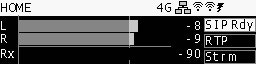
- PGM (L/R) level indicators in dBFS. The mark at 0 VU (-10 dBFS) is brighter. Avoid having the signal permanently exceed this level.
- Reception (Rx) level indicator for SIP calls.
- Network status (4G/Ethernet/Wi-Fi).
- Status of SIP, RTP, and streaming connections (active, off, or error).
- Battery level (plug in at 10%).
- Quick access to the SIP Contacts directory by pressing the encoder.
-
CONNECTION CENTER
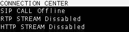
- Shows the three connection modes and their current status.
- Allows establishing or terminating each connection.
-
SETUP

- Shows active IP addresses.
- From here, access all configuration options:
- Wi-Fi
- Ethernet
- 4G Modem
- RTP Stream
- HTTP Stream (webcasting)
- SIP Account
- SIP Directory
- Battery Info
- Time Zone (for recordings)
- Firmware Version
-
RECORDING

- Displays and edits recording parameters for internal memory.
Channels
Microphones
- The MX2200 handles 3 microphone channels and supports a fourth shared with the MIC 3 fader.
- Gains are automatic, adjusting based on the fader position. This optimizes the signal-to-noise ratio and prevents preamp overload.
- The MASTER MIC button enables the microphones, sends them to PGM, activates the On-Air Light, and mutes headphone #1 (when an On-Air Light is connected).
- Microphones are not sent to CUE; they are only heard in headphones when they are in the program.
Microphone Compressor
- The dynamic compressor activates when exceeding the threshold of -10 dBFS (0 VU).
- High ratio, attenuating up to 20 dB.
- MIC COMP indicator with 3 states:
- Green: reaches threshold (-10 dBFS)
- Red: maximum attenuation, close to clipping (-5 dBFS)
- Clipping: indicated with a 3-second hold
About stereo mixes
Although the MX2200 transmits in stereo, the microphone channels generate a mono mix.
For stereo captures (e.g., ambient sound), an auxiliary console connected to the line input is required, typically using condenser microphones with phantom power.
Although the MX2200 transmits in stereo, the microphone channels generate a mono mix.
For stereo captures (e.g., ambient sound), an auxiliary console connected to the line input is required, typically using condenser microphones with phantom power.
USB and analog line
- The USB/LINE IN fader controls the USB audio if a computer is connected.
- If there is no USB, it takes the signal from the stereo analog input LINE IN.
- With USB connected, the LINE IN can be used via the telephone line control (PHONE) when the hybrid is not in use.
- To send to program: raise the fader. Optimal level when peaks reach 0 VU.
- To listen in CUE: press the CUE button above the fader.
USB Audio
When connecting the USB port to a computer, the operating system installs a USB recording device that receives the PGM mix.
When connecting the USB port to a computer, the operating system installs a USB recording device that receives the PGM mix.
Monitoring
- The CUE MONITOR control adjusts the level on all four headphone outputs.
- Any signal in CUE is sent to all outputs.
- The PGM button allows muting the program signal in the headphones to listen only to what is present in CUE.

Speaker/Monitor Output
- With an on-air light connected, headphone output #1 functions as a speaker output.
- This output is muted when microphones are activated to prevent feedback.
- Audio remains active on headphones #2, #3, and #4.
Talk to CUE
Pressing the TALK button in the CUE MONITOR area:- Interrupts the signal in the headphones.
- Sends the voice from the built-in microphone.
- Allows the operator to communicate with the team in headphones without shouting, gesturing, or removing them.